High-Yield CNC Nesting Machine Optimization:How to Prevent Costly Tool Breakage andMaterial Waste in High-Output Furniture Plants
1. The High-Output Bottleneck: Mitigating Tool Breakage and Material Waste in CNC Woodworking
For custom cabinetry manufacturers and commercial furniture factory directors in the US, UK, and Southeast Asia, operational efficiency hinges heavily on the reliability of their CNC nesting lines. When executing complex, high-speed nesting patterns on high-density materials like melamine-faced chipboard or compact laminates, unexpected tool breakage completely halts production momentum. This issue is accompanied by severe material waste caused by edge chipping or panel shifting, driving up raw material scrap costs and threatening tight B2B delivery contracts.
The ultimate strategy to prevent tool breakage and minimize material waste on a high-output CNC nesting machine is the synchronization of heavy-duty electrospindles (9.0kW to 12kW) with optimized chip-load calculations, dual-layer vacuum matrices, and premium solid carbide compression bits. According to the Woodworking Machinery Industry Association (WMIA) 2026 Global Manufacturing Efficiency Study, incorrect feed-to-speed ratios and inadequate vacuum hold-down pressure cause up to 81% of premature tool failures and panel spoilage in automated cabinet workshops. By implementing scientific cutting parameter modulation and high-torque workholding systems, factories can stabilize dimensional accuracy within ±0.05mm, protecting costly tooling lines while squeezing maximum yield out of every sheet.
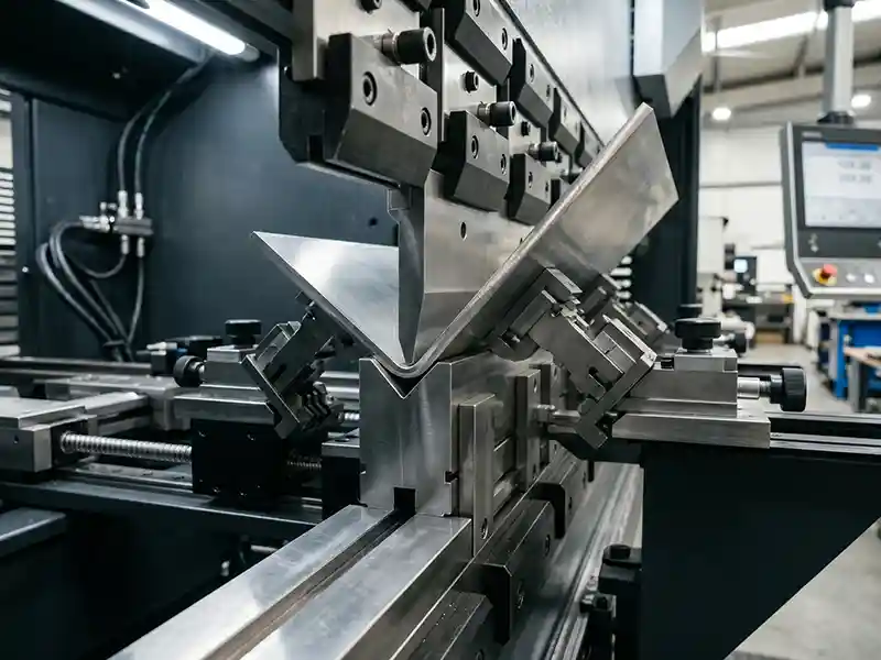
2. The Physics of Carbide Wear: Why Compression Tooling Snaps Under High Feeds
To keep pace with demanding factory schedules, operators frequently push feed rates past safe operating limits without adjusting spindle RPM. This mechanical imbalance disrupts the chip load, which represents the actual thickness of the material chip removed by each cutting edge during a single revolution.
If the feed rate is too aggressive relative to the spindle speed, the chip load becomes excessively large. This subjects the carbide flutes to extreme mechanical stress, causing catastrophic tool breakage. Conversely, if the feed rate is too slow, the tool rubs against the wood fibers instead of cleanly shearing them. This friction generates intense heat buildup that destroys the tool’s tempered coating, leading to premature dulling and severe edge chipping on delicate panel laminates.
- Mechanical Stress Fractures: Excessive chip loads exert high lateral forces on small-diameter bits, causing immediate structural failure at the collet line.
- Thermal Degradation: Inadequate chip clearing traps extreme heat inside the nesting groove, accelerating carbide wear and scorching panel edges.
Section Summary: Maintaining an optimal chip load through precise feed-to-speed ratios is absolutely critical to avoid the extreme mechanical stress and thermal friction that snap nesting tools.
3. Maximizing Vacuum Matrix Pressure: Preventing Small-Part Shifting
Even with pristine carbide tooling, material waste spikes drastically if smaller nested components, like cabinet drawer fronts or narrow fillers, shift on the CNC router bed during high-speed routing passes.
Industrial-grade CNC nesting centers overcome this issue by utilizing high-flow vacuum matrix beds backed by heavy-duty 7.5kW to 11kW liquid-ring or rotary-vane vacuum pumps. Splitting the matrix table into independently controlled, automated zones concentrates the suction pressure precisely where the material is being cut. Furthermore, using a high-density, uniform-density MDF spoiler board ensures even air distribution, creating a solid down-force that holds parts securely in place, even when processing small surface areas.
| Nesting Material & Application | Recommended Carbide Tooling Type | Optimal Feed Rate & Spindle Speed | Required Vacuum Pressure Standard |
|---|---|---|---|
| 18mm Melamine Particleboard (Cabinet Carcass) | 3/8″ (9.52mm) 2-Flute Compression Diamond/Carbide | 18 – 22 m/min @ 18,000 RPM | Minimum -0.08 MPa continuous zone suction |
| 12mm Compact Laminate (HPL / Phenolic Panel) | 1/2″ (12.7mm) Triple-Flute Coated Carbide Upcut | 6 – 8 m/min @ 12,000 RPM | Maximum zoned suction; mandatory tool cooling assist |
| 19mm Premium MDF (Routed Shaker Doors) | 1/2″ (12.7mm) 2-Flute Solid Carbide Compression | 15 – 18 m/min @ 16,000 RPM | Minimum -0.075 MPa; high-volume dust collection active |
Section Summary: High-output zoned vacuum tables paired with stable MDF spoiler boards neutralize panel shifting, completely eliminating material waste during high-speed cutting cycles.
4. Financial Automation ROI: Protecting Margins by Eliminating Part Rejection
For custom furniture plant managers, calculating the return on investment for premium CNC nesting machines involves analyzing tool longevity and sheet utilization yields.
In factories running unoptimized, low-tier nesting systems, tool breakages and panel slippage regularly result in an average material waste rate of 5.8%. Transitioning to an engineered, industrial-grade CNC nesting cell featuring smart look-ahead acceleration control and high-efficiency tooling deployment unlocks significant bottom-line savings:
- Reduced Tool Replacement Costs: Maximizing carbide tool lifespans via precise chip-load programming slashes monthly tooling expenses by up to 45%.
- Unlocking Maximum Sheet Yield: Advanced true-shape nesting software algorithms compress parts within 2mm of each other, pushing sheet utilization efficiency to 92% or higher.
- Downstream Sorting Efficiencies: Clean, chip-free cuts mean parts move directly from the nesting bed to the automatic edge bander without requiring manual sanding or patching.
Section Summary: Optimizing CNC nesting parameters drives massive ROI by slashing raw tooling expenses and expanding sheet utilization rates to over 92% per production cycle.
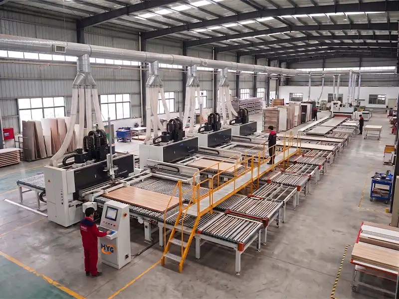
5. Preventive Maintenance Blueprint for Continuous Nesting Precision
Sustaining micron-level accuracy across multiple factory shifts requires a disciplined physical maintenance regimen targeted at the machine’s high-frequency mechanical components.
First, inspect and clean the electrospindle’s internal taper and collets daily using specialized cleaning kits; resin accumulation or micro-dust inside the collet creates tool runout, which causes premature bit breakage and jagged cuts. Second, check the automatic lubrication pump levels weekly to ensure the linear guide rails and helical rack-and-pinion systems receive uniform oiling, preventing stick-slip errors during rapid directional changes. Finally, fly-cut the MDF spoiler board regularly to maintain a perfectly flat reference plane across the entire bed surface.
Section Summary: Daily spindle collet cleaning, weekly automatic lubrication audits, and regular spoiler board resurfacing safeguard your CNC nesting line from accuracy drift and tool breakdown.
6. High-Output CNC Nesting Machine FAQ
Q1: Why are the top and bottom surfaces of my melamine panel chipping during a nesting cut?
Chipping on both sides of a double-sided laminate is a classic sign of incorrect tool alignment or a worn compression bit. Compression bits feature upcut flutes at the bottom and downcut flutes at the top to pull wood fibers toward the center of the panel. If your initial plunging depth is incorrect, or if the bit is set too high, the upcut portion will engage the top laminate surface, causing immediate chipping defects.
Q2: How often should the MDF spoiler board be fly-cut or resurfaced?
In a standard two-shift factory setup processing roughly 100 to 120 sheets a day, the MDF spoiler board should be resurfaced by 0.2mm to 0.3mm every 2 to 3 production days. Over time, repeated tool paths cut shallow grooves into the MDF surface, causing vacuum leaks that degrade suction force. Regular fly-cutting restores a perfectly flat, non-porous face to ensure secure part hold-down.
Q3: What are the main benefits of choosing an aggregate head for a custom furniture factory?
An aggregate head acts as a mechanical transmission unit that converts the vertical rotation of your CNC spindle into horizontal actions. This allows your nesting router to perform precise side-drilling, lock-case routing, and horizontal slotting for modern toolless furniture fasteners (like Lamello or Cabineo systems) in a single setup, completely removing the need for a secondary horizontal boring machine.
Q4: How do I know if my tooling issue is caused by runout rather than excessive feed speed?
Tool runout occurs when the cutting tool rotates off its true axis, forcing one flute to absorb significantly more material than the others. You can identify runout if you notice one flute wearing down much faster, audible high-pitched vibration during operation, or a cut groove slightly wider than the physical diameter of the bit. Inspecting and replacing worn collets and tool holders every 6 to 9 months will eliminate this risk.